Introduction of ER Model
The Entity Relational Model is a model for defining the entities that should be recorded in the database and for depicting the relationships between those entities. The enterprise schema that the ER data model describes graphically depicts a database’s overall logical structure.
The relationship between the entities found in the database is described by the entity relationship diagram. A person, a car, a firm, and their relationships with one another are all real-world things that are modeled using ER models. ER Diagram, in a nutshell, is the database’s structural format.
The high-level data model in DBMSs is called ER model. It is used to depict a logical understanding of the system from a data perspective and stands for the Entity-Relationship Model. Before constructing your database, it is recommended that you create an ER model in DBMS since it makes it simpler for developers to comprehend the database system by simply glancing at the ER model. It creates a conceptual database design that offers a very clear and uncomplicated view of the data. ER diagrams, which are diagrams created to build a database, are used in ER models. Entities, characteristics, and connections between them form the foundation of ER diagrams.
The relationship between entities that will be recorded in a database is illustrated in an entity relationship diagram (ER Diagram). The ER Diagram is essentially a database’s structural design. It serves as a framework built using specialized symbols to define the connections between database elements. Entities, attributes, and relationships make up the three main parts of an ER diagram.
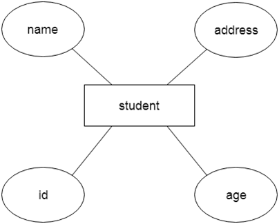
For example, Let’s say we create a database for a school. The student will be an entity in this database with properties like address, name, id, age, etc. There may be a link between the address and another entity with properties like city, street name, pin code, etc.

Why Use ER Diagrams In DBMS?
- It is simple to transform ER diagrams into relations (tables) since they are used to represent the E-R model in databases.
- ER, diagrams serve the function of modeling items in the actual world, which makes them quite valuable.
- ER, diagrams don’t need any hardware support or specialized technical expertise.
- Even a novice user may easily generate and comprehend these diagrams.
- It provides a common method for logically visualizing the data.
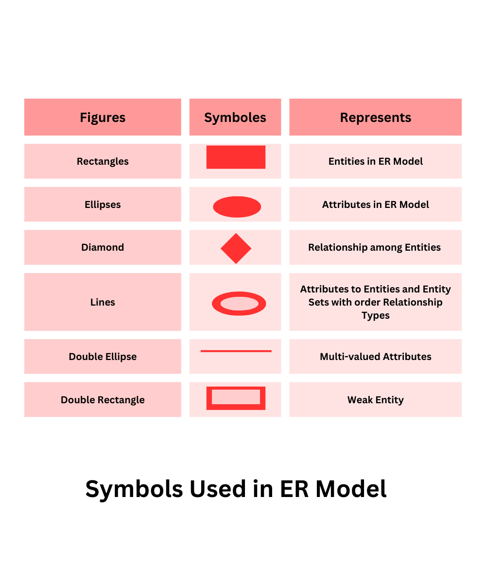
Symbols Used in ER Model

The logical view of the system is represented by the ER Model, which includes the following symbols, from the data perspective:
- Rectangles: In the ER Model, rectangles stand in for Entities.
- Ellipses: Ellipses are used in the ER model to indicate attributes.
- Diamond: Relationships between entities are symbolized by diamonds.
- Lines: Lines show properties for entities and entity sets that have different connection kinds.
- Double Ellipse: The double ellipse symbolizes multi-valued attributes.
- Double Rectangle: The Double Rectangle symbolizes a Weak Entity.
How to Draw ER Diagram?
- The first step is to identify each entity, put it in a rectangle, and name it appropriately.
- The next phase is to determine their relationships, pace them using the diamond by those relationships, and ensure that no relationships are interconnected.
- Add the appropriate characteristics to the entities.
- Eliminate unused entities and connections.
- Add the appropriate colors to emphasize the database’s data.
ER Design Issues
We learned how to create an ER diagram. Additionally, we went over several approaches to defining entity sets and the connections between them. We also comprehended the numerous design forms that depict a connection, an entity, and its characteristics. However, users frequently misunderstand the ER diagram’s parts and design process. As a result, the ER diagram develops a complicated structure and has several problems that do not match the traits of the business model used in the actual world.
Here, we will discuss the basic design issues of an ER database schema in the following points:
1) Use of Entity Set vs Attributes
The structure of the real-world enterprise being simulated and the semantics attached to its properties determine how an entity set or attribute should be used. When a user uses the main key of one entity set as an attribute of another, it results in an error. Instead, he ought to make use of the connection to do so. Additionally, although we identify it in the relationship sets, the main key characteristics are implicit in the relationship set.
2) Use of Entity Set vs. Relationship Sets
It might be challenging to determine whether an entity set or relationship set can best explain a given item. The user must choose a relationship set for expressing an activity that takes place between the entities to comprehend and decide on the appropriate usage. It is best to keep the entity set separate from the object if portraying it as a relationship set is necessary.
3) Use of Binary vs n-ary Relationship Sets
connections presented in databases are often binary connections. Nevertheless, several binary connections can serve as representations for non-binary interactions. For instance, we may construct and describe the ternary connection ‘parent’, which can refer to a child’s mother, father, or both. A similar connection may be shown by the two binary relationships that a mother and father can have with their kid. As a result, a non-binary connection can be represented by a collection of unique binary relationships.
4) Placing Relationship Attributes
The arrangement of the relationship characteristics can be influenced by the cardinality ratios. Therefore, rather than using any relationship set, it is preferable to link the characteristics of one-to-one or one-to-many relationship sets with any participating entity sets. The choice of whether to include the provided property as a relationship element or entity attribute should reflect the characteristics of the actual business being represented.
For example, if an entity may be identified by the combination of the participating entity sets rather than being identified as a distinct entity. A many-to-many relationship set must be connected to this kind of property.
Therefore, it necessitates having a thorough understanding of all the components that go into designing and modeling an ER diagram. The fundamental necessity is to assess the real-world enterprise and the relationships between various entities and attributes.
